Project
06/2011 - 08/2011
Bluetooth accelerometer
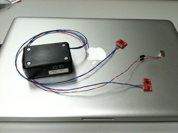
is a startup in the developing solutions in the health and wellness industry. Our first project involved sensing vertebrae orientation using a 3-axis accelerometer. We wanted to be able to collect the data from the accelerometer wirelessly so that someone could wear the device and not be tied to a computer. We chose to use a bluetooth link because it was the easiest to implement and afforded us the most flexibility. We used an arduino because it allows for rapid deployment with minimal time spent on code. We even had the time to find a pretty plastic enclosure for our project (picture to the left). I must say that even though it took a lot of extra time, it was worth the effort. When a project is well encased, it is much more durable and you won't need to be re-soldering loose wires constantly.
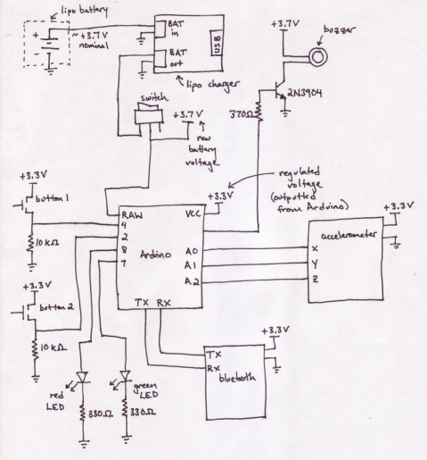
Circuit schematic for bluetooth accelerometer
We decided to power the circuit off of a single LiPo cell for simplicity and elegance. We purchased a battery recharging circuit from sparkfun allowing us to recharge the LiPo cell using a mini USB connector. The switch disconnects the entire project from the battery, minimizing battery drain when not in use. Buttons and LEDs are wired directly to arduino ports for simple inputs and outputs A buzzer (motor with off-center weight) is wired up using a NPN transistor. We wired the buzzer this way because it requires 75 mA which is just a little too much for an Atmel chip to source from an I/O pin. The accelerometer connects directly to 3 ADC pins on the arduino. The bluetooth module (RN-41) talks to the arduino over the serial line. This is very inconvenient when you need to reprogram the arduino as you must first disconnect the bluetooth module, otherwise it interferes with the communication.


Here's a little video showing bluetooth communication between the arduino pro mini and my laptop. Current consumption is monitored so that I can see how much current each subcomponent is using. The arduino and the bluetooth module use about 35mA of current combined. The LEDs use 5mA each, and the buzzer uses about 80mA.
ClearEar Project
03/2011 - 06/2011
Pressure sensor
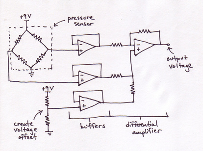
After a successful PCB project, ClearEar came back to us with a related project. They were worried that their system might cause harmful pressures inside the ear canal and they wanted some way to measure the pressures during a simulated operation. After searching around online, we decided to buy a simple pressure sensor and solder up a simple gain stage using an LM6484 op-amp. We used a 5 volt dc wall wart to power the system and zip tied the cable to the protoboard for strain relief. We used a dip socket to house all the resistors so that if we needed to change the value of a resistor (to increase the gain or change the dc bias) we would have a very easy time.


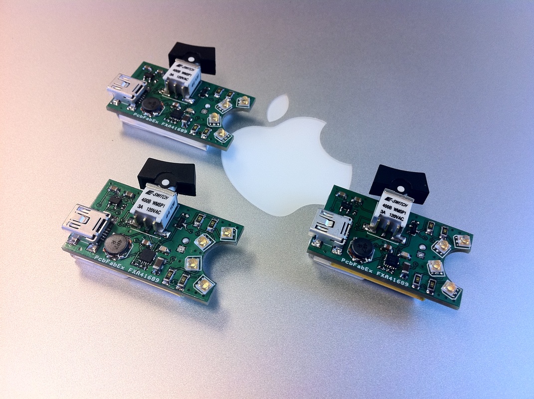
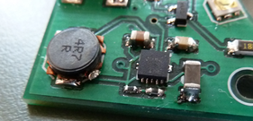
Just got the boards back fully populated and decided to take some pictures. Notice that all the components are the same as the previous board, they're just arranged in a much tighter fashion. I'm glad to say that after soldering on the battery, these boards worked right out of the box (recharging circuit too)!


New layout
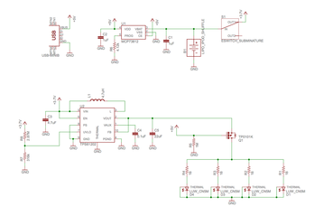
ClearEar Design Rev 1.0 (LED circuit)
ClearEar was very happy with the first PCB we made for them and after some trials, decided to change the shape of their device. They wanted to the PCB to fit their new form factor and asked us to adjust the layout accordingly. We were able to squeeze the size of the PCB down to just slightly larger than the battery.


First PCB
ClearEar, a local medical startup, approached us because they needed a lighting solution for their medical device. They contracted us to design the electronic portion of the system. They required a small form factor high intensity lighting solution that was rechargeable. After tossing a few ideas around, we decided on the circuit pictured to the left. It features a very elegant single cell LiPo battery, a boost converter to get the required voltage for the LEDs, a battery charging chip, and some ultra small, ultra bright, narrow beam white LEDs. We also added a MOSFET to prevent the LEDs from turning on when the battery is charging (this was to prevent the extra current drain from messing up the charge cycle. A toggle switch turns the LEDs on and off. When the battery voltage drops below 2.5 volts, the boost converter circuit automatically shuts off and prevents the circuit from over discharging the LiPo. Any mini USB cable can be used to recharge the battery.


